Overview
Most likely the most complex system you’ll build out for your skoolie or van is the electrical system. While it was the most complex part of our build and we are still making improvements, it was also the most fun I have had throughout our build. But being so complex, means that it can be easy to mess up without proper planning. This comprehensive guide will walk you through everything you’ll need to consider before, during, and after you build your electrical system. It’ll also cover the things we forgot to think about so hopefully you don’t repeat our mistakes.
What this guide will address
In this guide we’ll talk about how we built our electrical system from battery to 120 volt outlet. We’ll show you all the components, explain how they work, and why they’re important. We’ll talk about energy efficiency and some of the ways we try to conserve power and use only what we need to. We’ll do our best to help you plan for what you need based on how much power you expect to need.
What this guide won’t address
This guide will pick up where our shore power electrical system guide left off. That means this guide will not cover installing the power inlet and running wire into the main disconnect, though those components are likely necessary for your build if you are reading this article. If you are starting from scratch, I suggest starting with that guide, then moving to this guide when you are ready.
This guide will also not cover building a 12 volt electrical system or solar power. We have separate guides planned for those topics. Some pictures in this guide may contain other items that do not pertain to this specific guide. Our bus currently has a full electrical system with 12 volt power via a fuse box, 120 volt power via an inverter, all powered by a battery bank. I built our system in pieces while I learned so the pictures displayed here are from different stages of our build.
I am not an expert (seriously, I am not an electrician). I have meticulously researched every aspect of our electrical system and made sure we built it in a way that we could easily test and retest everything before we actually switched the power on. But mistakes are still possible and they still happen. Any work you do on your bus/van/car/spaceship/etc. you do at your own risk. This is how we built our electrical system. If you do not know what you are doing you can seriously hurt yourself or someone else. Wiring your system incorrectly can lead to a fire, electrocution, and a whole bunch of other nasty stuff. Please be very aware of yourself, your tools, and what has power running to it at all times when working on your electrical system. Do your research and do not take my word for it. I have shocked myself more than once setting up our system and trust me, it’s not fun. Again, any work you do on your build, you do at your own risk.
Without further ado, here is what you need to know to plan and build your 120 volt off-grid electrical system.
Components of an off-grid electrical system
We’re going to use a lot of terminology throughout this guide and while you’re likely to know what batteries and power outlets are, it’s going to be important to understand what every part of your system does and why it’s important. There are a lot of options out there for these components and their similarities and differences vary from “it doesn’t matter, use whatever you want” to “if you’re using this, you must use this or else everything will explode”. Like I said, I’m not an expert, so you’re not going to come across the latter situation in this guide, but the options exist. Anyways, these are the components that will make up most off-grid electrical systems.
Batteries
Batteries are where you will store all of your energy for your off-grid electrical system. Batteries will be wired together in series or in parallel to create a 12 volt, 24 volt, or 48 volt system. Wiring two 12 volt batteries together in series would create 24 volts of output at the same amp hour capacity as one of the batteries. Wiring two 12 volt batteries together in parallel would create 12 volts of output at the sum of the amp hour capacity of both of the batteries. There are a few battery types out there, but the most popular are Lithium-ion and AGM. There is plenty of information out there on the pros and cons to each. I went with AGM for our build, but Lithium-ion are likely the more popular option for off-grid electrical systems at this point.
Renogy Deep Cycle AGM Battery (200ah) – Check price on Amazon
Battle Born Deep Cycle Lithium-Ion (LiFePO4) Battery (100ah) – Check price on Amazon
Like I said, we went the AGM batteries since they were significantly cheaper. They do have some downfalls and the main one being they should never be drained completely to preserve the life of the battery. Lithium-Ion batteries do not have this limitation, but are significantly more expensive. Whichever you choose you will want to make sure they are compatible with the inverter you choose. The one we used accepts a number of different battery types so we had flexibility there and could choose to upgrade down the line.
Battery Cable Wire – 1/0 AWG to 4 AWG
Transferring lots of power means using thicker wire. The higher the AWG/gauge, the thinner the wire. In order to wire the batteries in an electrical system together you do not want them to be limited by the size of the wire. Also, the more power running through the wire, the more the wire will heat up. This can be a fire hazard! Do not skimp on wire gauge and test your system early and often! I used 1/0 AWG wire to wire my batteries together in parallel as well as to run power to my inverter.
1/0 AWG Wire – Check price on Amazon
4 AWG Wire – Check price on Amazon
Wire Lugs or Terminal Lugs
Wire lugs are crimped on to the ends of wire to attach that wire to the various components of the electrical system. You’ll likely need a couple different sizes based on what wire you are using and what you will be connecting your wire to. The lug/terminal is crimped to the wire to make sure it cannot come loose. People will often push solder into the terminal to improve the connection and ensure the wire cannot come loose. This isn’t entirely necessary however. You can also buy various gauge wire at various lengths with the different terminals you need preassembled if you don’t want to make cables for all of your connections.
I used 3 different sizes based on the wire size I needed (1/0 AWG or 4 AWG) and the size of the terminal I was connecting to (3/8 or 5/16).
1/0 AWG 3/8 Terminal Lug – Check price on Amazon
1/0 AWG 5/16 Terminal Lug – Check price on Amazon
4 AWG 3/8 Terminal Lug – Check price on Amazon
Heat Shrink Tubing – Check price on Amazon
Heat Shrink Tubing is used to seal the area between the insulation on the wire and the terminal. Heat Shrink Tubing should not be used to hold the terminal in place. It is solely to protect the wire and reduce the conductive surface to just what is needed to make a solid connection. A lot of times this comes with the wire or terminals you purchase.
Power Distribution Blocks – Check price on Amazon
Power Distribution Blocks allow you to quickly and easily split power from a wire in multiple directions. Wires with terminals attached can be placed over a post on an active Power Distribution Block to send power through that wire. While this is not completely necessary it makes it easier to add, remove, or isolate components in your electrical build. It also helps keep your build organized. The ones we used had 3/8 inch terminals which is why a lot of our terminal lugs were 3/8 inch.
Battery Switches – Check price on Amazon
Battery Switches work like any other switch but are rated for higher current than a switch you would use further along in your build like a light switch or rocker switch. I used big marine battery switches to cut power to my 12 volt system as well as to the inverter. This allows you to quickly and safely cut power to the rest of your system if you need to work on it or add a new component. By using these switches you can make sure that all your connections are tight before actually running a current through them. It’s always better to have multiple easy ways to cut power in case of an emergency. We have two on/off switches and one 3 position switch in our system. The 3 position switch allows us to direct power either to our inverter or directly to our panel.
12 Volt Circuit Breakers – Check price on Amazon
12 Volt Circuit Breakers work just like the circuit breakers in your house or assuming you have a 120 volt system, in your skoolie or van build. If more electricity than the breaker is rated for tries to travel through the breaker, it will trip, breaking the connection and preventing damage to the rest of your system or causing a bigger problem. Once tripped, a circuit breaker can be reset. Circuit Breakers are generally used for higher electricity applications. The number of amps you need will depend on what you are protecting with the circuit breaker. We are protecting a 3000 watt inverter using 12 volt electricity so we needed 250 amps. Calculate your amps based on watts and volts.
Inverters
Inverters are used to convert battery power usually stored at 12, 24, or 48 volt direct current electricity into 120 volt alternating current. They are generally rated in watts ranging from 500 watts to 5000 or more watts. Inverters can come with a lot of different features and options such as built in transfer switches, battery chargers, etc. Sometimes they will have power outlets built in or allow you to run power into a load center to build circuits off that. I’d recommend getting a good inverter that can do everything you need it to do which very likely includes charging your batteries. This will make your electrical system a lot less complicated. There are a lot of options and they vary in price. We chose an AIMS 3000 watt pure sine inverter. It does everything we need it to (which we’ll get into in this guide) but didn’t break the bank (that much). I have not personally used them but I have heard great things about the Victron products. Especially if you plan on using solar panels, Victron is worth looking into. The price points are a lot closer than they were in 2020 when we were deciding on what to use.
AIMS 3000 Watt 12 Volt/120 Volt Pure Sine Inverter/Charger – Check price on Amazon
Victron Energy MultiPlus 3000VA 12 Volt Pure Sine Wave Inverter/Charger – Check price on Amazon
Load Center (Breaker Box) – Check price on Amazon
A Load Center or Breaker Box is a box generally made out of galvanized steel that holds, organizes, and protects all of your circuit breakers. The load Center is one centralized location that receives and distributes power wherever you might need it in your electrical system. It includes pre-cut holes that can be punched out when you need to run wire in or out of the box.
We did talk about this in our Shore Power guide but considering we will wire this from our inverter rather than the main disconnect this is worth mentioning again. If you followed that guide to the end you likely already have one of these.
Breaker Box Grommets – Check price on Amazon
Breaker Box Grommets are small rubber rings designed to be inserted into the punched holes in your Load Center to protect the wires running through those holes. This is particularly important as the wires run into the box of an off-grid electrical system are likely to move and vibrate. This movement can eventually cut through the insulation on the wire and cause a short in your electrical system.
AC Marine Wire (kinda like Romex) – Check price on Amazon
AC Marine Wire is similar to Romex which generally contains three wires in one. The three wires would be the hot wire, the common wire, and the ground wire. AC Marine Wire is stranded wire where Romex is solid wire. Stranded wire is generally recommended for off-grid electrical systems as solid wire is more likely to break with all the vibration you would expect in an off-grid electrical system.* In standard Romex wire, the ground wire is usually bare and uninsulated. In the AC Marine Wire I recommend, the ground wire is actually insulated as well.
*This is often disputed and a common argument is that RVs use solid wire. We decided to use stranded wire since it is sturdier but it may not be completely necessary.
Insulated Staples – Check price on Amazon
Insulated Staples are used to attach wire to wooden fixtures in your off-grid electrical system. It is important that the staples be insulated to make sure the wire you are securing is not touching metal that could cut through the insulation on the wire. The plastic insulation on the staple is a lot stronger than the wire insulation and protects the wire while the staple secures it.
Electrical Switch and Outlet Box – Check price on Amazon
Switch and Outlet Boxes are used to house standard outlets and switches. They are generally made of plastic but can also be made of galvanized steel and are secured to studs inside walls. They hold the switch or outlet in place and provide some space where stripped wire can be connected to the outlet or switch. I recommend the plastic ones as if you use metal you will need to use rubber grommets to protect wire running to or from your box.
Wall Outlets (Duplex Receptacle) – Check price on Amazon
Wall Outlets or Duplex Receptacles are standard electrical outlets like you likely have throughout your home. This is where you would plug in your various appliances that need electricity from your 120 volt electrical system.
Switch Plates and Outlet Plates
Switch Plates and Outlet Plates are used to cover the space around your switch or outlet. They screw into the switch or outlet they are covering and leave a hole for the face of your switch or outlet.
Switch Plates – Check price on Amazon
Outlet Plates – Check price on Amazon
Other items you may need but are covered in our Shore Power guide
- Power Inlet – Check price on Amazon
- 50 Amp Wire – Check price on Amazon
- Main Disconnect/50 Amp Load Center – Check price on Amazon
Tools needed to build an off-grid electrical system
You’ll need a few tools to build out your off-grid electrical system. Chances are you’re already aware of a lot of these and likely already own a lot of them. We’ll talk about these in the context of your electrical system, but almost all of them are used for a lot more than we’re going to mention.
Various Screwdrivers
Throughout your build you’ll need a ton of different screwdrivers. A set from Harbor Freight will do just fine, but since building our Skoolie I bought this Makita set for general use. I have since bought a few more to make sure I always have one in our bus, our home, and my tool bag wherever I take it. It has all the traditional heads, square heads often used by electrical parts, torx heads, and a few socket sizes. It ratchets and comes with a sturdy and neat case. Highly recommend.
Socket Wrench and Socket Set
A Socket Wrench and Sockets may be used to loosen and tighten hex bolts and nuts. This gets more common when working with larger wires. The batteries we used in our electrical system used a hex bolt to attach wires to the threaded battery terminal as well as to secure the wires to our inverter. Sockets will come in both SAE and Metric sizes. Again I recommend grabbing these at Harbor Freight.
SAE and Metric Wrenches
SAE and Metric Wrenches would offer another way to loosen and tighten metric bolts and nuts. You may not always have enough space to fit a socket and socket wrench, so a traditional wrench might be a bit more useful in this scenario. Again I recommend grabbing these at Harbor Freight.
Adjustable Wrench
An Adjustable Wrench would also be used to loosen or tighten hex bolts and nuts. It’s useful when you are working quickly with ample space and have a lot of different sized nuts and bolts, or you don’t have the exact size wrench or socket you need. Again I recommend grabbing this at Harbor Freight.
Hammer
As it relates to your electrical system, a standard claw hammer is useful in installing staples to keep your electrical system organized and secure. Again I recommend grabbing this at Harbor Freight.
Utility Knife
A standard Utility Knife is useful for stripping large wire or stripping the outer insulation from AC Marine Wire or Romex. Harbor Freight has a great curved utility knife thats perfect for electrical work.
Wire Strippers and Crimpers – Check price on Amazon
Wire Strippers and Crimpers are used to quickly strip the insulation from wire in order to make a connection. A good pair of wire strippers will usually have a spot to crimp ring terminal or quick disconnect connectors as well as wire cutters.
Battery Cable Lug Crimping Tool – Check price on Amazon
Wire Lugs and Terminals need to be crimped onto the wire. Depending on the size of the wire this can be difficult to do by hand but good crimpers will offer a variety of sizes and give you a lot of leverage when crimping. The ones I got came with cable cutters as well and I used it to build all of our battery cables including the 1/0 AWG wires.
Outlet/Receptacle Tester – Check price at Home Depot
An Outlet/Receptacle tester is a three-pronged device designed to be plugged into your electrical outlets to test if the outlet is wired correctly. They will generally have three lights used to indicate if the outlet is wired correctly and let you know roughly what is wrong in the event that it is not.
Non-contact Voltage Tester – Check price on Amazon
A Non-Contact Voltage Tester can tell you if there is power is running through a wire or component of your electrical system. It’s a useful tool in troubleshooting something that is not working as expected or making sure something is not electrified before beginning to work on it.
Questions to consider before building your off grid electrical system
There are a number of factors you will need to consider before investing in your off-grid electrical system. Ultimately you can ask yourself these questions to determine what components you should be considering. We’ll go over these in more detail as well.
- Do you need an inverter capable of pure sine wave output or can you use modified sine wave?
- Are you running a 12, 24, or 48 volt system?
- Should your batteries be AGM, Lithium-ion, or something else?
- What level of output do you need to power all your appliances?
Do you need an inverter capable of pure sine wave output or can you use modified sine wave?
This one is sort of an easy one. Are you planning on charging a computer or running any complex devices (like a computer, television or monitors, or audio systems) on your 120 volt electrical system? If so you need a pure sine wave inverter. Basically, inverters can create the 120 volt power the fast and dirty way (modified sine wave), or the clean way (pure sine wave). It’s a little more complicated than that, but will do for our purposes. I’ll go out on a limb here and say if you need to convert from 12 volt to 120 volt you likely also need pure sine wave.
Are you running a 12, 24, or 48 volt system?
Maybe this is determined by your inverter selection? Maybe it’s determined by your battery bank? I like a 12 volt system because you can run certain things like lights, phone chargers, water pumps for your plumbing system, lights in RV ovens, etc. without any extra hassle. But if you were able to salvage any parts this decision may have been made for you. You can always convert to the voltage you need and that may be less expensive in the short term.
Should your batteries be AGM, Lithium-ion, or something else?
We personally went with AGM. They are significantly cheaper than Lithium-ion, but we can’t count on using their full capacity. We would need double the amp hours to do the same as someone using Lithium-ion which means double the battery bank size. That comes with a lot of extra weight and storage space. Both types you can get sealed and can travel in a vehicle safely and maintenance free, but you’ll want to make sure that is the case for the specific batteries you purchase.
What level of output do you need to power all your appliances?
Only you know what you’ll need. We tried to think about power as conservatively as possible. We planned to use propane for cooking and heating water, and diesel to heat the bus itself. We planned to use 12 volt for absolutely anything we can. We chose not to use contact chargers for our phones because they are less efficient than plug in cord chargers. It really comes down to planning and how much electricity you use regularly. You can purchase devices to measure your electricity use to help determine which products you should use and what you can live without.
When should you start building your electrical system?
If we’re speaking honestly, I was pretty nervous to begin working on our electrical system. I had to piece together tons of articles and videos before I felt confident in what I was doing. It can also be one of the most expensive pieces of your build which makes it even harder to get started. I believe I put it off for a little too long, and wished I had done a number of things differently.
If I were to do it over again, I would start working on the electrical system immediately following demolition and the initial framing. (This would require you to plan your layout so you know where you will need outlets as well.) Since we had insulated first, installing things like the Power Inlet meant we were cutting away insulation to fit it. The beauty of spray foam insulation is that done properly and at the right time, there will be no gaps in insulation. Unfortunately that is not the case in our build. We had also installed the ceiling prior to planning the electrical system. We did not leave space for the LED puck lights we wanted to use and after installing the ceiling, we did not have a ton of space to work with. We compromised by running most of our lights at about eye level with a slight downward angle. Ultimately it worked out, but left a lot to be desired.
Building the 120 volt off-grid electrical system
I expect this is the part of the post most of you have been waiting for. Your 120 volt electrical system is what will provide power to all of your standard wall outlets. A 120 volt system will be essential for powering anything you cannot run on your 12 volt system. This might include computers, monitors, televisions, certain cooking equipment like toasters or microwaves*, a refrigerator, or anything else you might plug into the wall at home. While certain manufacturers might make 12 volt versions of these appliances, they’re likely a bit pricey. Take our fridge for example. We bought our 10.1 cubic foot fridge for about $400. It’s a standard 120 volt appliance. We compared other options before purchasing it including a 12 volt fridge from GE. At double the price (at the time of writing this) it offered slightly less space, and being pretty new to the market, we couldn’t be too sure how long it would last or how reliable it might be. If I’m being completely honest, the 12 volt fridge is looking pretty attractive option so it might not have been the best example, but I digress.
*If you plan to power large appliances you will want to make sure you do your research into what kind of power those devices require. Heat is the most inefficient use of electricity. I recommend looking into other power sources (like propane) if the appliance you are trying to power produces heat.
Your 120 volt off-grid electrical system will be made up of a few parts. Put simply you will need to store electricity in batteries, you will need to draw electricity from those batteries and deliver it wherever you need power, and you will need a way to charge your batteries back up after using them. In our Shore Power guide we went over how to bring electricity into your skoolie and run it straight into a load center. The key to your 120 volt system is putting an inverter and charger between your main disconnect and your load center.
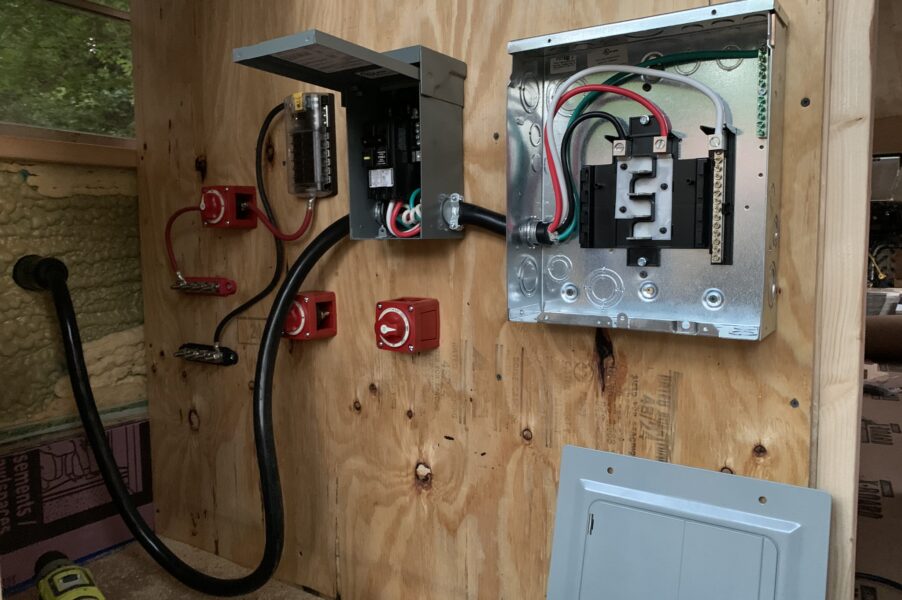
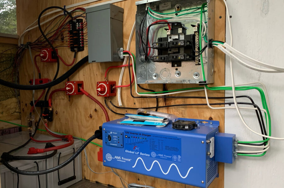
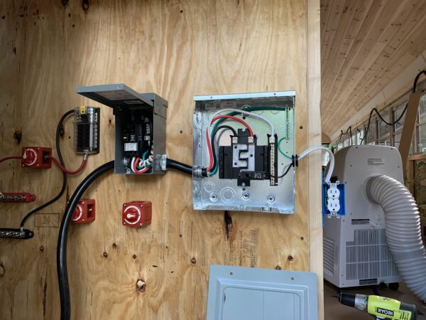
As you can see from the pictures above, we have a 50 amp cable coming from our power inlet and through our main disconnect. In the picture on the left another 50 amp cable delivers power to the load center. In the picture on the right, four separate wires leave the main disconnect. Those wires are the same gauge as the wires that make up the 50 amp black cable but we need them to route a little differently. The red wire runs to a 3 position switch. We’ll get into why in a little bit but for now let’s focus on the green, black, and white wires. The green is our ground wire, the black is our hot (+) wire, and the white is our common or neutral (-) wire. (The red wire is also hot.) All three wires run from the main disconnect into the right side of the inverter.
How the inverter works
In our Shore Power article, power was delivered from outside the bus from our shore power source. Once you have your batteries and inverter set up, power will be delivered to wherever you use it from the inverter. Even if you are plugged in to a shore power source. The inverter will take in all power sources* (shore power and battery power) and determine what to do with it based on how much power there is and what power is being drawn.
*If you have solar power your inverter will likely not handle that directly.
The inverter we chose was the AIMS 3000 Watt 12 Volt Inverter/Charger. The “Inverter/Charger” part is how the device interacts with your batteries. It has the ability to charge them when connected to a power source and the ability to draw power from them and “invert” to output 120 volt power. So the Inverter/Charger can take in 120 volt AC and output 12 volt DC or vice versa. This is part of the reason I recommend you get an all in one unit. I have read the manual for our device cover to cover a dozen times and I still call it “Our Magic Blue Box”. I don’t know how it does everything it does; it just does. From this point on I’ll just be referring to it as our “inverter”, but know it does both.
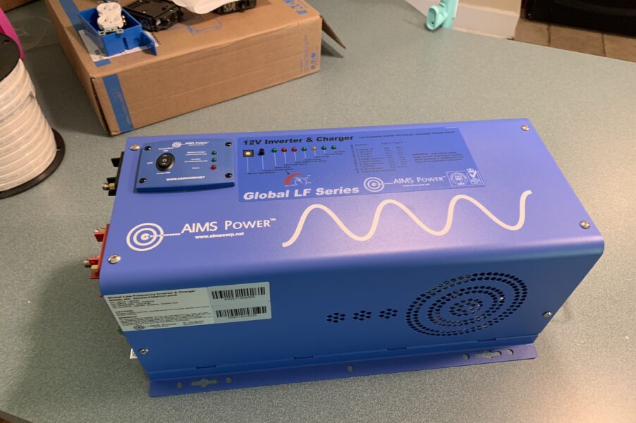
Our inverter has a 12 volt side (left) and a 120 volt side (right). On the 12 volt side there is a red/positive (+) terminal, and a black/negative (-) terminal. These connect to their corresponding terminals on your battery bank. On the 120 volt side of the inverter there are two sets of terminals each accepting 3 wires. One is input and one is output. When the inverter is running, there is always power coming out of the output on the 120 volt side. If there is power running to the inverter (like when there is a power source plugged into the inlet on the outside of the bus) our inverter is taking that power and splitting it, and sending some straight back through the output on the 120 volt side and sending some to the 12 volt side to charge the batteries. This is a feature of our inverter. Others may work or be set up to work differently. This was a desirable feature for us because it means we could plug in without needing to shut the system down. If there is not power running to the inverter (like when the bus is not connected to a power source), electricity is drawn from the battery bank on the 12 volt side, inverted to 120 volts, and passed through the output on the 120 volt side of the inverter.
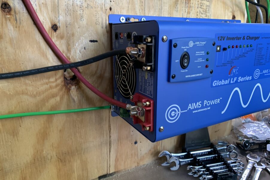
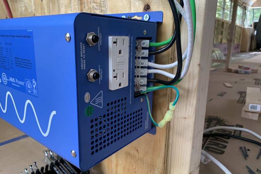
The last wires you see pictured in our set up are the green wire on the 12 volt side and the looped green wire on the 120 volt side (both pictured above). The green wire on the 12 volt side in the picture above is the ground for the whole electrical system. It runs directly to the metal body of the bus. This was described in the owners manual for our inverter. The looped green wire on the 120 volt side means that the common and ground may be connected. This may be different for your application so I suggest reading the manual to determine the correct configuration for your set up.
The inverter is likely the most expensive component in your 120 volt electrical system. Inverters cost anywhere from the low hundreds to the low thousands. The price is generally reflective of the watt output rating as well as the various features it offers. The more features, the less you need to worry about during set up but it may also mean that more can go wrong with each component.
How the battery bank works
As I mentioned before, we decided to go with Renogy Deep Cycle AGM Batteries. They were cost effective, came in 12 volts, and up to 200 amp hours. We started with one as we learned how to build our system and upgraded to two to increase amp hours. How you set you set up your battery bank is mostly determined by how many volts you want to output. We chose to go with 12 volts because that made it easier to work with our 12 volt electrical system for things like lights and phone chargers. That 12 volt decision led our decision on which inverter to buy as well but you could let your inverter decision determine your battery set up as well. If you go with anything other than 12 volts for your battery bank you would likely just need a converter like the Victron Energy 24/12-Volt DC-DC Converter (if you’re using 24 volt) to build a 12 volt system for your lights or any other 12 volt devices.
Since we decided to go with a 12 volt system, our batteries were easy to come by. Most large deep cycle batteries are 12 volts. Since our batteries were already outputting the correct voltage, to tie the batteries together we needed to wire them in “parallel”. This meant that we would connect the positive side of the first battery to the positive side of the next battery, then do the same with the negative side. Wiring our two batteries together in parallel meant that the battery bank would still only output 12 volts, but would now be a combined 400 amp hours. If you had four 6 volt 200 amp hour batteries, you could wire two and two in series, then wire each of those banks in parallel and get the same result as I just described. Thats not what we did so not going to go much further there but just so you know.
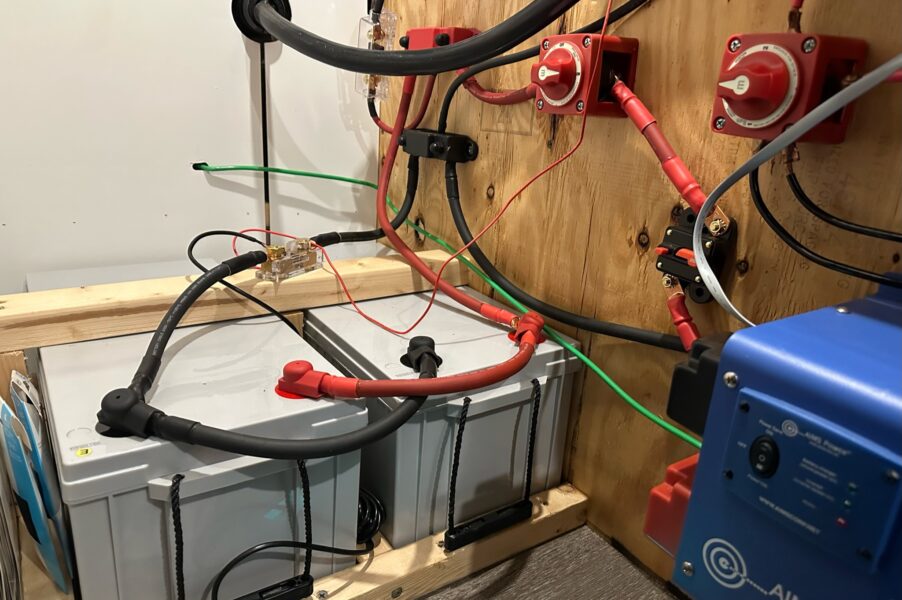
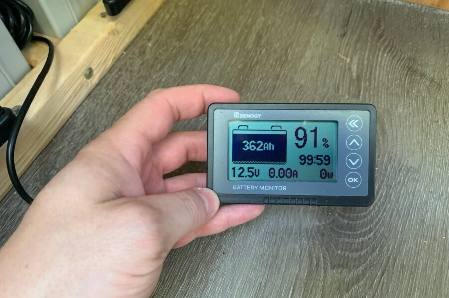
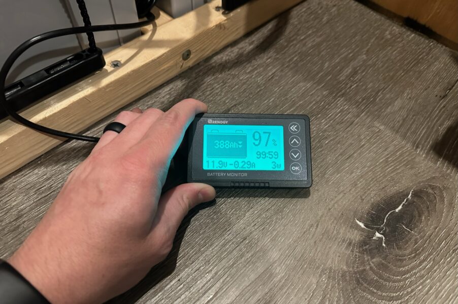
It is worth mentioning these batteries are huge and very heavy. Just one weighs about 127 pounds. As you can see from the picture above, there are two wires coming off of each battery terminal. One is being used to connect to the other battery. The other travels to the corresponding positive or negative bus bar. On the negative side between the battery and the bus bar is a shunt. This allows us to watch the draw of the battery and measure its capacity in real time using a display from Renogy. We’ll get into that below. From each bus bar another wire connects to the inverter. On the negative side the wire runs directly to the inverter. On the positive side the wire runs to a switch allowing us to cut power to the inverter and then to a 250 amp inline circuit breaker.
Running power into the load center and to your outlets
So now that we understand how power enters the inverter (either from shore power or from the battery bank) we can talk about the output on the 120 volt side of the inverter. Just like the input that we talked about above, the output has terminals for our hot wire (black), common wire (white), and ground wire (green). You do not need to use these colors but it is much easier to visualize what is going on if you do. All of these wires are going to go straight into your load center. This works the same way as it did in the Shore Power guide with the exception that we no longer have two hot wires. We are missing our red wire because our inverter is only capable of 120 volt input or output. Other inverters may not have this caveat and in that case you would be able to avoid our 3 position switch solution and just wire to the second leg of the load center.
The three wires coming from your inverter’s output on the 120 volt side will run into the load center/breaker panel. Make sure you use rubber grommets any time you have wire passing through metal!
Your green ground wire will run to the ground bar in your panel. Ours did not come with one and we needed to purchase and install it separately. This bar is where you will run your grounds for any circuits you build out of this panel.
Your white common wire will run to the common bar. In our load center it is on the right and has black plastic behind it. The large terminal at the top is where you will install your white wire. This bar is where you will run your common wire for any circuits you build out of this panel.
Finally, your black hot wire will run to one of the two remaining terminals. You will see metal zig zagging down the panel where you will connect your circuit breakers. If you only run power to one of these terminals only half of your circuit breaker positions will work. You could optionally split the power from your black wire to the other leg then all your circuit positions would work. The only issue with that is we still have our red wire coming in from our main disconnect. If we want to use our full 50 amp power potential, we’ll want to leave the other leg open for that.
Thats it! Once you have connected your ground, common, and hot wires from your inverter’s 120 volt output to your load center you are ready to start building circuits. This part is the same as the Running a circuit section of the Shore Power guide so feel free to consult that if you’re not 100% sure what to do next. Just make sure you fully understand what you are doing before you do it, and always turn off any power before working on your system.
Other components of your electrical system
Bus Bars – Check price on Amazon
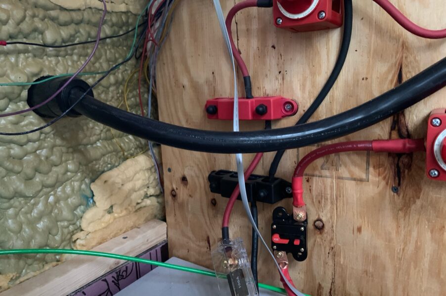
Depending on the complexity of your system these may not be necessary, but since we were planning for a 12 volt system and an inverter for a 120 volt system, these bus bars were lot easier to tie into when we needed to.
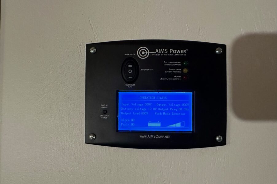
Inverter Control Panel – Check price on Amazon
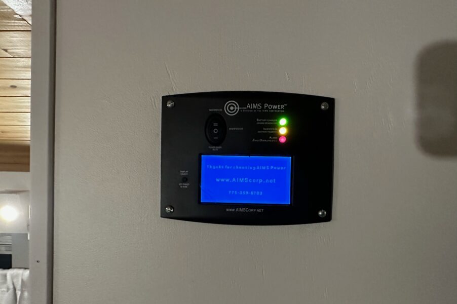
Since we built our electrical system in what we consider the “garage” of our skoolie, we needed a way to control and monitor our system from the cabin portion of our build. We went with a control panel designed for our inverter and suggest you do the same. Victron has great support for this and even includes an app that allows you to monitor from your phone.
Battery Usage Monitor – Check price on Amazon
Unlike the inverter monitor, this battery monitor displays our stats as they relate to the battery bank in real time. This way it includes the draw from the 12 volt system as well as the 120 volt system. It does not include stats specific to the inverter however.
Our 3 position switch solution
I have mentioned our “3 position switch solution” a few times in this guide. The reason we need this solution is we have opted to use a 50 amp power inlet. We chose that because we can always convert down and use power from a 20 or 30 amp source using an adapter. In the picture below you can see we have a regular extension cord plugged into our 50 amp inlet. When you do that, that power is just split into two legs and provided on two wires. If we don’t connect it to anything, the power won’t go anywhere as if it was not split at all. But if we are connected to a true 50 amp shore power source, what if we wanted to use that other leg of power? Or better yet be able to switch between using that leg of shore power or splitting the output of the inverter?
The next part of this guide is pretty advanced and to be honest I’m not 100% sure you should do it. Do not do this unless you are an electrician or you have consulted an electrician. I am not joking.
The 3 position switch allows us to connect a wire to one position, a second position, or no positions. Generally your main wire would be a power source, then you could send that power in one direction, another direction, or no directions. It would work backwards as well. Theoretically, if we connected the second leg of the load center to the terminal on the switch that was always connected, we could choose between one power source (the second leg coming from the main disconnect), another power source (the output from the inverter), or no power source for that second leg. Additionally, by passing through that terminal with the black wire from the output of the inverter on our way to the first leg in the load center, that will always be connected since the wires make contact there. This is set up in the picture below.
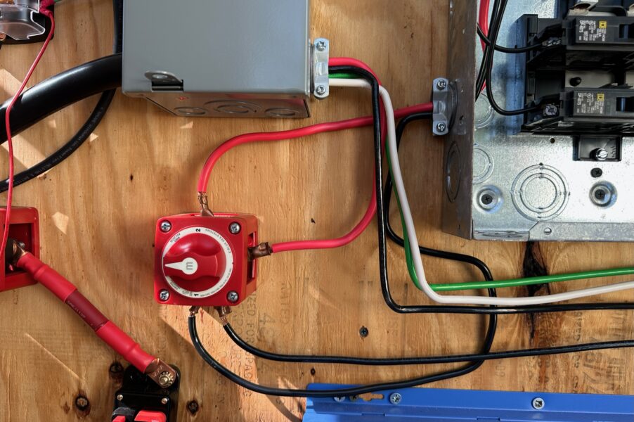

The benefit of doing this would be ensuring that we can charge our batteries while connected to shore power, but also have certain circuits within our build that are capable of powering appliances that we couldn’t or shouldn’t through the inverter alone. An example might be an air conditioner. Maybe we couldn’t power it or don’t want to power it regularly if we are conserving energy, but when we are plugged in why not?
Thats about it. I’m sure there is plenty of work to do from here but I hope this guide helps. Please be careful and make sure you truly understand what you are working on.
 by
by 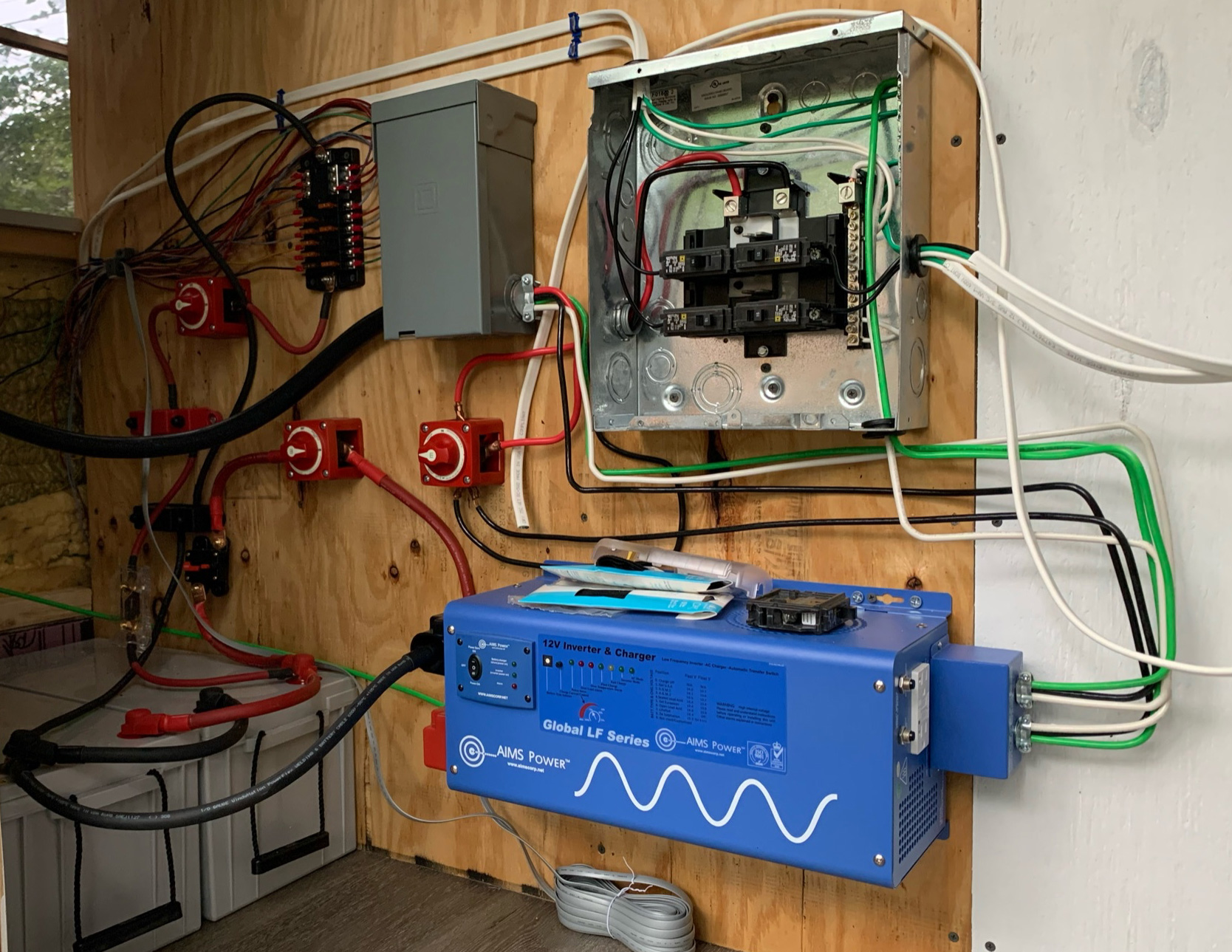


 by
by