 by
by 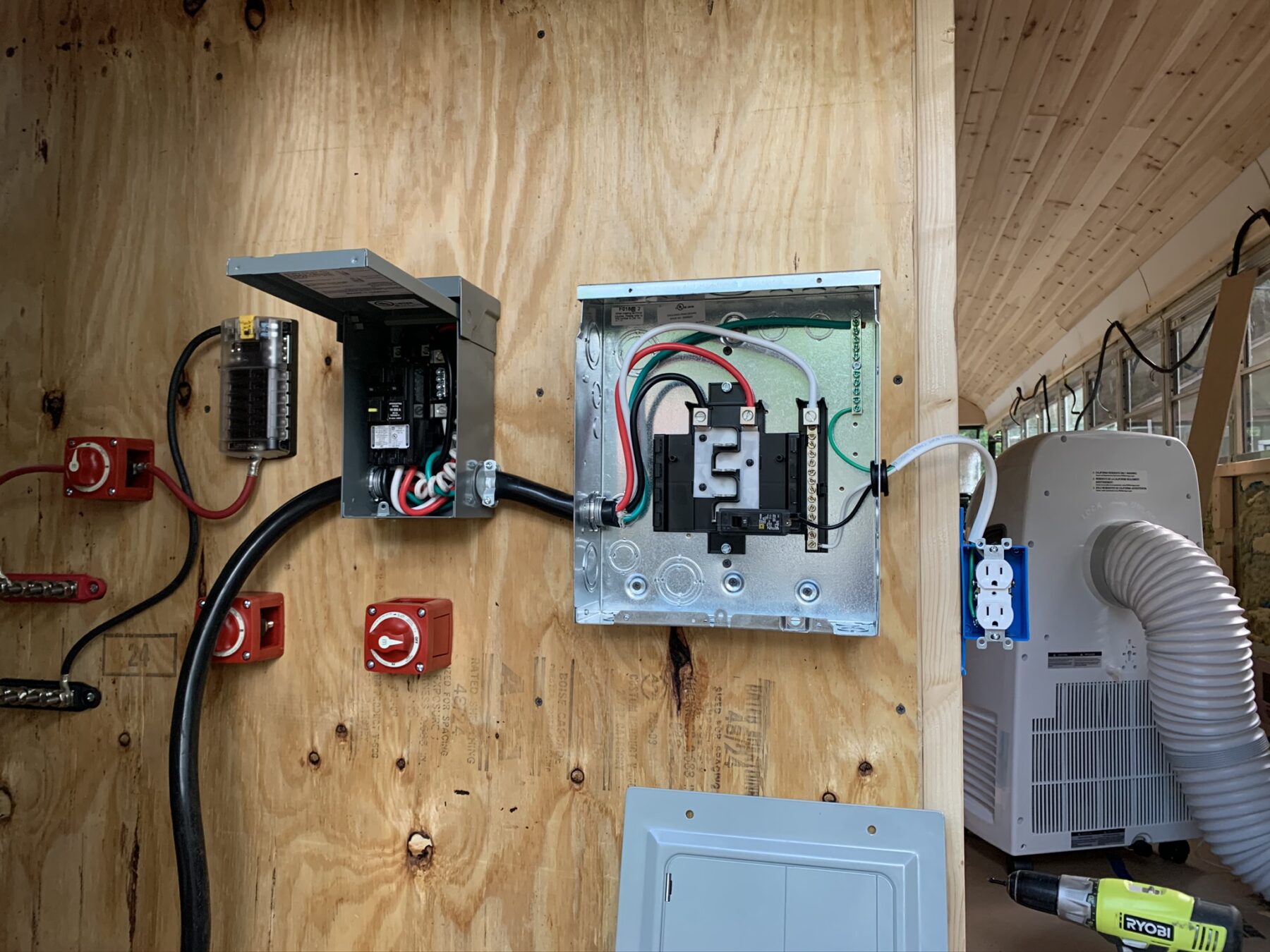
Overview
When reading forums or Facebook posts in the various skoolie or van groups I am a part of I often see people looking for information on specific electrical builds. One I see more often is an electrical set up for someone who plans to have shore power wherever they stop, so they want to avoid the headaches and cost that goes along with a full blown off-grid electrical system. They just want to park, plug in, and have power where they need it. If that’s you, then this guide is for you.
What this guide will address
This guide will go over everything you will need to build a simple electrical system in your van or skoolie. It will define the various components of such a system and the products you will need to build a simple electrical system yourself. It will educate you on what the various components are used for and how to safely install them. This guide will show you how you can run an extension cord outside of your bus to get power to electrical outlets in your van or skoolie.
What this guide will not address
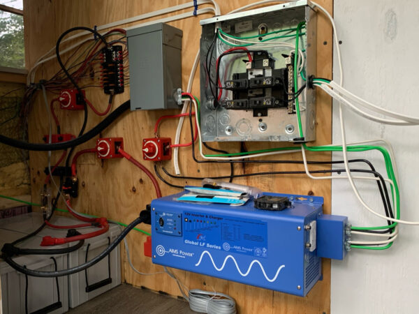
This guide will not cover anything that would allow you to have power while not directly plugged in to a power source. (If that is what you are looking for, please check out our skoolie off-grid electrical system guide.) This includes but is not limited to solar power, batteries, or inverters. We have guides for all of these components, but this guide will remain dedicated to building a shore power electrical system. Some pictures in this guide may contain other items that do not pertain to this specific guide. Our bus currently has a full electrical system with 12 volt power via a fuse box, 120 volt power via an inverter, all powered by a battery bank. I built our system in pieces while I learned so the pictures displayed here are from different stages of our build.
Before we get started I should mention, I am not an expert (seriously, I am not an electrician). I have meticulously researched every aspect of our electrical system and made sure we built it in a way that we could easily test and retest everything before we actually switched the power on. But mistakes are still possible and they still happen. Any work you do on your bus/van/car/spaceship/etc. you do at your own risk. This is how we built our electrical system. If you do not know what you are doing you can seriously hurt yourself or someone else. Wiring your system incorrectly can lead to a fire, electrocution, and a whole bunch of other nasty stuff. Please be very aware of yourself, your tools, and what has power running to it at all times when working on your electrical system. Do your research and do not take my word for it. I have shocked myself more than once setting up our system and trust me, it’s not fun. Again, any work you do on your build, you do at your own risk.
Without further ado, here is what you need to know to plan and build your shore power electrical system.
Components of a shore power electrical system
We’ll try to provide as many pictures of the components we use as well as links to product pages from Amazon, Home Depot, or wherever else we might have purchased something. These are the products we actually used and we recommend them because they have worked well for us. These are the components or products needed to build a shore power based electrical system.
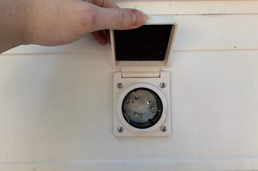
Power Inlet – Check price on Amazon
Power inlets come in different “sizes” with the common ones being 15 amp, 30 amp, or 50 amp. I recommend building your system for 50 amps as you can always use adapters to use lower power sources or extension cords. Setting up your system for 50 amps will give you the most versatility.
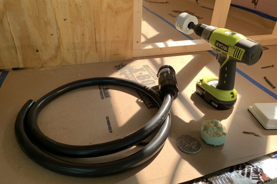
50 Amp Wire – Check price on Amazon
There are a few ways to get 50 amp wire. You can buy it by the foot at Home Depot (its the same wire you might use to wire an outlet for an electric oven and range), or you can buy a 50 amp extension cord on Amazon or from an RV store and cut it up. I found the extension cord to be a little easier to work with and about the same price so thats what I went with and what is linked above. Either way you want 4 color coded 6 gauge wires. The gauge of the wire is important as you want to make sure it will not overheat under a heavy electrical current.
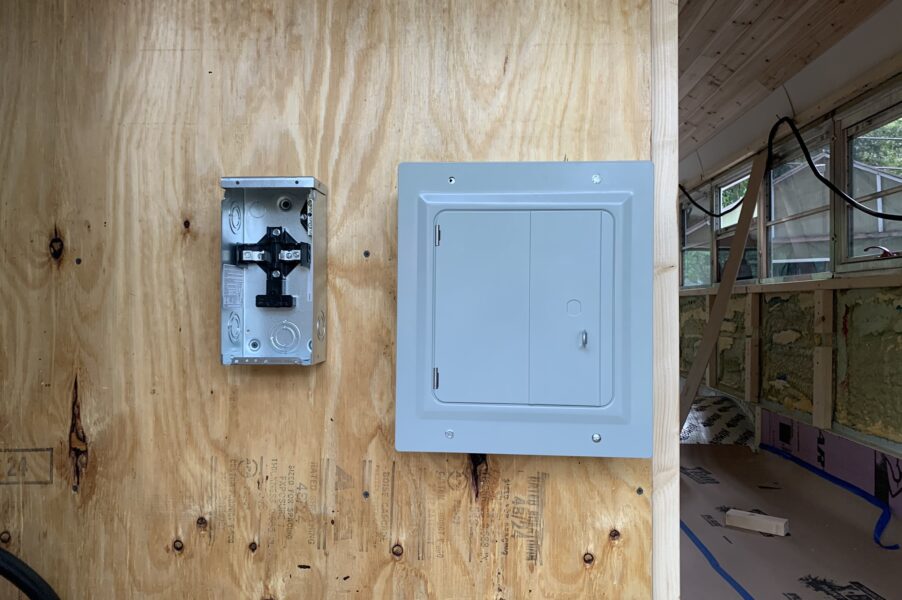
50 Amp Load Center – Check price on Amazon
The 50 amp load center protects the rest of your system and can act as a disconnect for the entire system as well. Basically the four wires enter this box, run through a 50 amp breaker, then exit the box and enter our next component; the 125 amp load center or “breaker box”. The GFCI breaker included with this panel prevents more power than we want surging to our main panel. It is designed for outdoor use so you might see it referred to as a “spa panel”. It may be overkill, but with this being installed in a skoolie, the GFCI functionality was important to me.
125 Amp Load Center (Breaker Box) – Check price on Amazon
The 125 amp load center will house all our breakers and will be where all our circuits start. I used a pretty small one with 8 spaces which was overkill for our skoolie. Space to upgrade is always good though and they don’t make them much smaller than that. This panel (load center or breaker box) will receive power from the 50 amp load center and distribute it to the individual breakers when they are installed. You may need to buy the ground bar separately and screw it into the panel yourself.
Marine Wire – Check price on Amazon
Homeowners or people familiar with electrical work might recognize this wire and call it Romex. It is similar with a couple key differences. The biggest difference is Romex wire tends to be solid where what we want is stranded wire. Stranded wire is recommended in skoolie and van builds as it is less likely to break by vehicle vibrations where solid wire can become brittle. The other difference is the ground wire in Romex is generally bare or uninsulated where this marine wire has a green insulation. Other than that it works the same way. Three wires wrapped in a jacket. The black wire should be used as the hot wire, the white wire as the common wire, and the green wire as the ground wire.
The rest of these materials you can pretty reliably pick up as you need at just about any hardware store but here are some buying options as well.
Circuit Breakers
Almost anything you wire would require a 15 amp circuit breaker. A 15 amp circuit breaker will be sufficient for running any outlets or lighting you might be running in your van or bus.
Grommets and Cable Clamp Connectors
I’d recommend Cable Clamp Connectors over grommets. These are incredibly important as you need to be careful anywhere metal and wire touch. As your vehicle moves, loose wires can chafe and short.
Electrical Boxes
Whichever boxes make the most sense for your build. I’d recommend going with the blue plastic ones. The ones I got were shallow so they fit easily in the space between the spray foam insulation and the wall.
Outlets
I used the cheapest 125 volt outlets you can get at Home Depot. You can get them for less than $1.00.
Installing your shore power electrical system
Time to put all the components together and provide power to your build. As a reminder, electricity is dangerous and you need to make sure you fully understand what you are doing before trying any of this yourself. That may include doing more research or consulting an electrician.
Planning your setup
You can start building your electrical system wherever you like but I want to stress the importance of planning your system. If you are building a skoolie or van, you know space is limited and you need to make sure everything you install takes up the smallest possible footprint. If you are starting small with a shore power only electrical system you may want to consider if thats permanent or if down the line you might eventually want to install solar panels (which will need a charge controller and a battery bank) or an inverter (which would also require a battery bank). You’ll also want to consider a logical flow for all the wires you’ll need now or down the line.
I found it useful to draw out the various components of the system and draw lines between the components that would need power. This system is pretty straight forward as the electricity is only flowing in one direction, but when planning our whole set up with battery bank, inverter, and 12 volt system, the lines for all the wires quickly got out of hand. Another issue with drawing it out was nothing was drawn to scale. It was impossible to know if everything was actually going to fit the way I had laid it out.
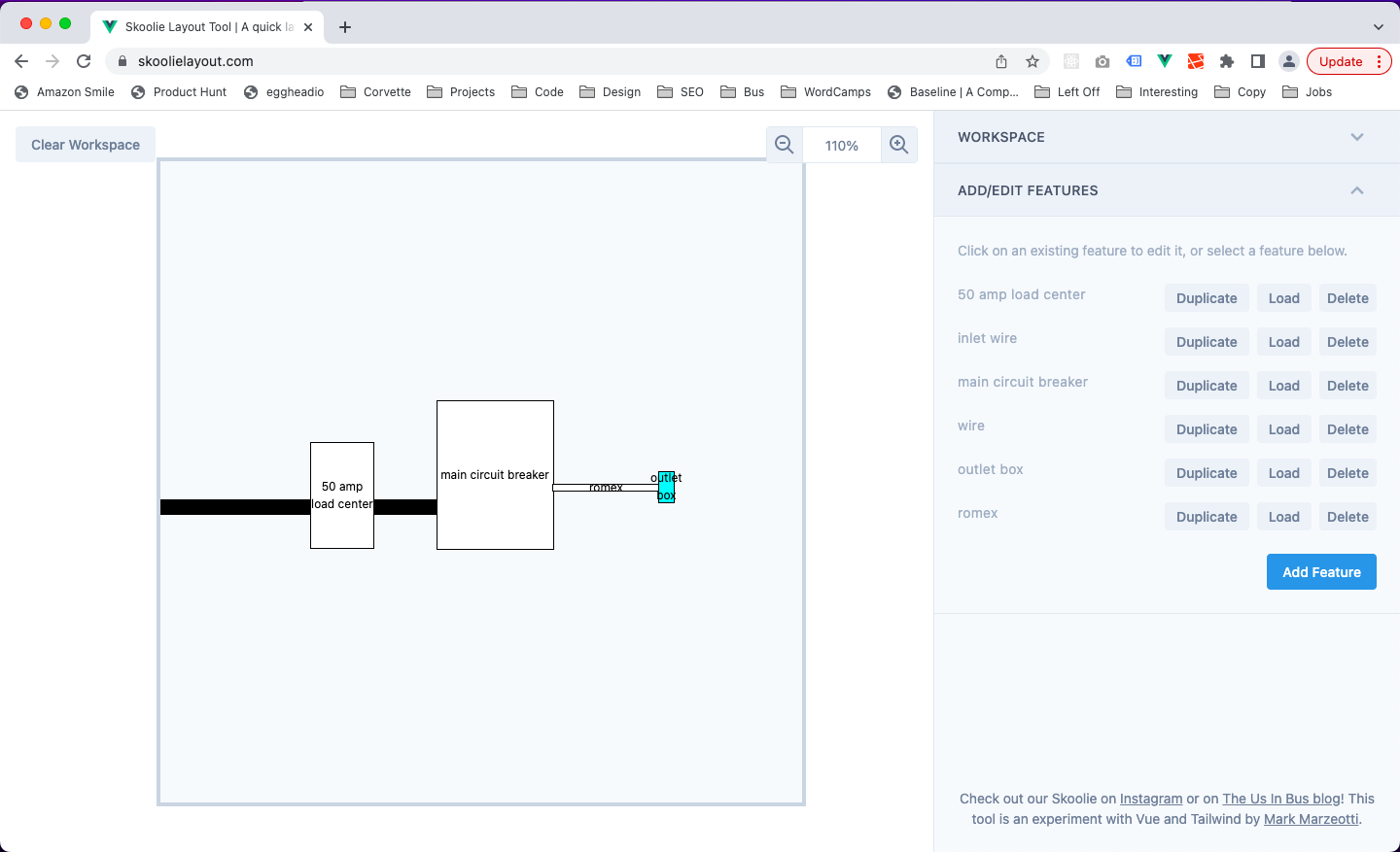
To solve this problem, a lot of people measure and make paper cut outs for the various components. You might see this most often for skoolie or van floor plans, but it works just as well for planning your electrical set up. I took a slightly different approach. I actually built an app that would allow me to create different components, label them, specify their exact size, and move them around to try different layouts. I ended up releasing it for free at skoolielayout.com. Give it a shot and hopefully it saves you some time.
As part of the planning process you might want to think about what sort of materials you will be installing everything on. I would avoid attaching any electrical component to the body of the vehicle or any metal attached to the body of your vehicle unless that is its specific function (like the inlet we are about to install). Likely you will be installing everything on a wood surface. Once you have decided on where the various components will go, it’s time to get our hands dirty.
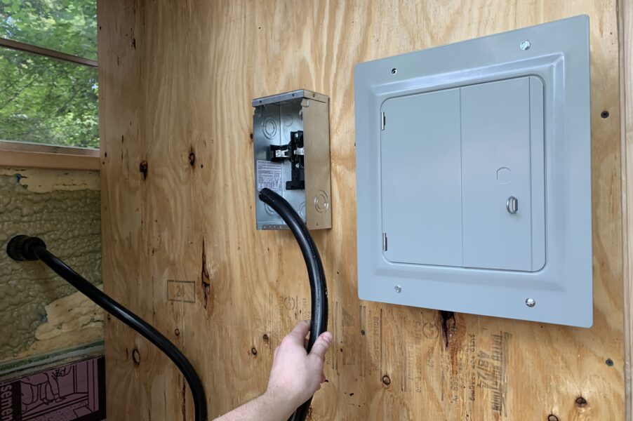
Installing the power inlet
It’s very important to read the instructions of any product you plan to install, and follow those even if they differ from what we are suggesting here. If you purchase an inlet similar to the one we have, the first thing you will need to do is measure and cut a hole to mount your power inlet through. The instructions should tell you what size hole to cut exactly and I would recommend getting a set of hole saws for this purpose. I bought the Milwaukee Hole Dozer very early on in our bus build and have used the various sizes countless times.
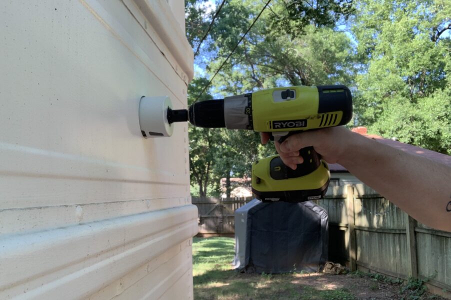
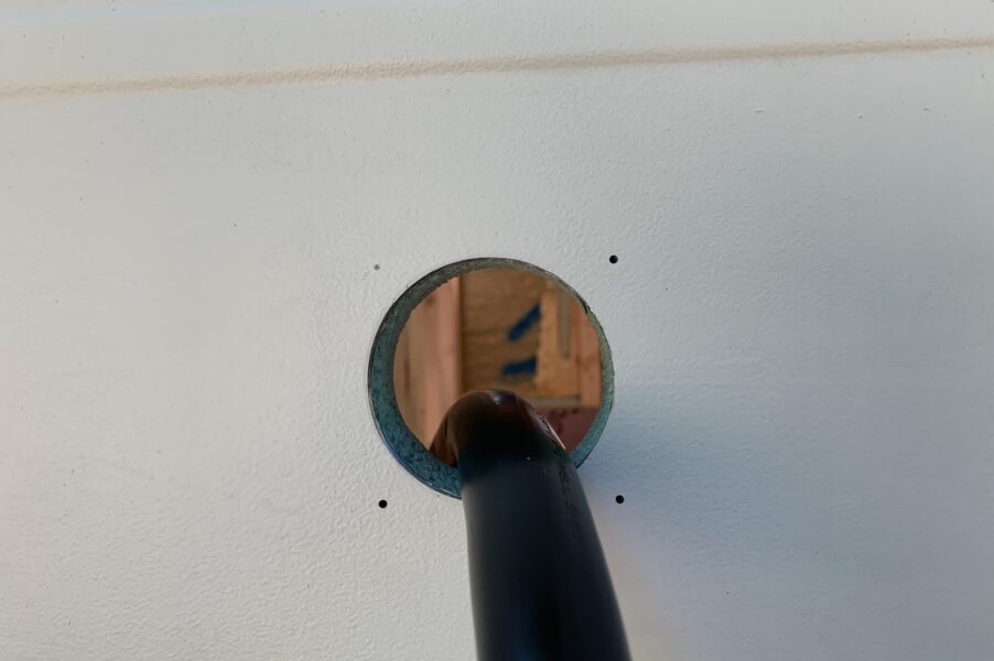
Plan where you want your inlet to enter your van or skoolie. We chose the drivers side as most RVs have their hook ups on that side. Make sure that you have a large flat surface on the outside so the inlet gasket can make a solid connection and drastically reduce the chance of leakage now and in the future. Notice from the picture above the hole is more or less vertically centered between the ribs on our bus. On the inside make sure you are not going to drill through any ribs or structural material. I knew that anything above that bottom rib pictured meant there was only sheet metal on the other side. The hole was also centered on the rear window meaning I would not hit the hat channel inside the bus either.
After your hole is drilled you’ll need to drill pilot holes for the screws that actually fasten the inlet to your vehicle. Make sure you don’t jump ahead and actually install the screws as attaching the 50 amp wire in the next step is much easier to do before the inlet is installed. Line the inlet up in the hole, make sure its level(ish), and drill, or mark and then drill the pilot holes. I marked the hole with a mechanical pencil through the inlet, but whatever you are comfortable with. If your inlet does not come with screws (mine didn’t) it should tell you what size and type of screws to use. I followed the instructions and picked up some 1 inch pan head stainless steel sheet metal screws that fit through the holes in the inlet. I drilled my pilot holes at about 75% of the screws diameter as is a good rule of thumb.
Connect the 50 amp wire to the power inlet
There should be instructions that come with the inlet, and on our inlet, the connections were marked green, white, red, and black, making it pretty obvious the connections that need to be made. You will need to cut this wire (plus a whole bunch more) so I’d suggest investing in a large wire cutter. I bought a crimping and cutting tool set that did the trick. Not just yet, but soon you’ll also need to attach terminals to some large gauge wire and this crimping tool can handle up to 1/0 gauge wire.
You will need to make sure your 50 amp wire will be long enough to reach your 50 amp panel. When I did this for the first time, I avoided cutting the wire to any specific length as long as I could. This stuff is expensive so I do not want a 3 foot length thats just barely too short.
Strip the heavy outer black insulation on your 50 amp wire. If you’re using an extension cord like we did, cut the head off the male side. (I suggest the male side because the power inlet actually comes with a male connector as well. If you have enough wire left over you may be able to use the rest and repair the male side and have a working extension cord again.) You’ll want to strip about 3 inches of the black insulation. I found using a utility knife to work as I had no wire strippers even close to big enough for the 50 amp wire. To my knowledge they don’t even make wire strippers this large, plus you’ll only have to do this a couple times so it would not make much sense to purchase even if you could. When cutting the outer insulation, make sure not to cut too deep as you really want to leave the individual wires insulation in tact. I took my time and was extremely careful and have had no issues.
Once the four internal wires are free, you’ll want to strip about a half inch of insulation off each of them to make you connection to the corresponding terminals in the power inlet. Most inlets should allow you to loosen a screw, insert the wire, and tighten the screw to clamp the wire in place. The whole inlet assembly should screw together with gaskets to make sure no water can get in to where the connections are made.
Unfortunately I do not have any pictures for this process, but will work on getting some. If you use this guide or have pictures we are missing we’d be happy to give you credit for them.
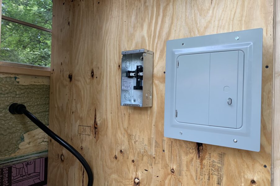
Mount the panels (breaker boxes)
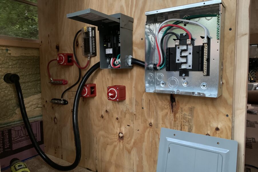
We mounted both panels to a sheet of 3/4 inch plywood. I just used regular wood screws to mount them but used about 2 screws in the first panel, and 4 in the second to make sure they were secure. Make sure that where you mount them will leave enough room for you to manipulate a length of 50 amp wire between them. The first time, I mounted the panels too close together and found it impossible to work the wire between the boxes. Thats why you will see in the final build, the wire goes almost straight across between the panels.
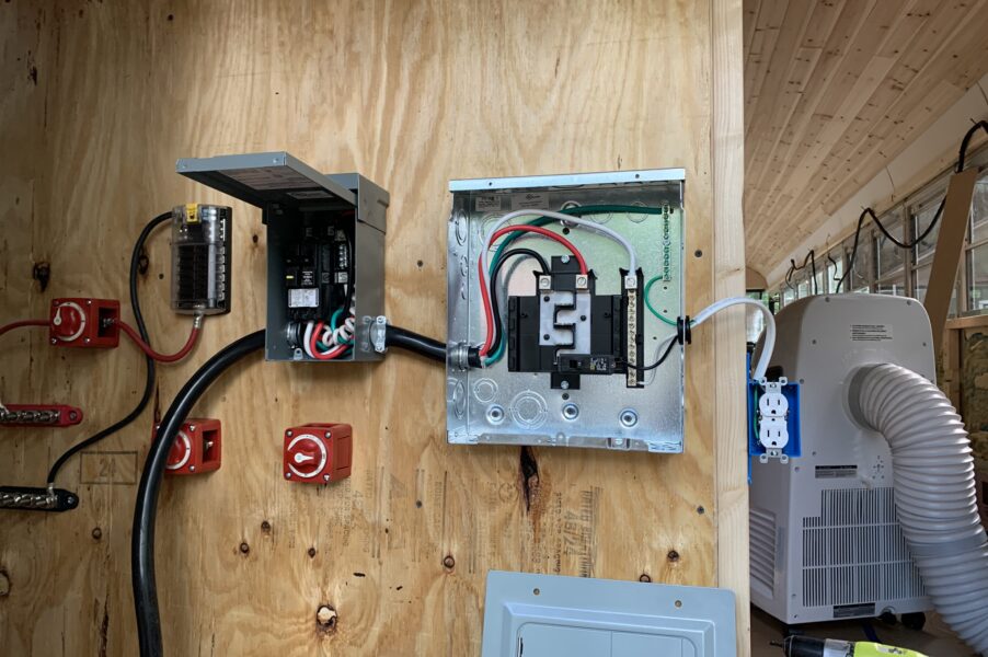
Wire the inlet to the first panel
By now you should have two panels, and a power inlet installed. That power inlet should have a length of 50 amp wire long enough to reach inside 50 amp breaker panel (the smaller box). Use a large cable clamp to hold the wires in place. You will need to knock out a proper sized space in the panel to install the cable clamp. You will also need to get cable clamps large enough for the 50 amp wire. I believe the cable clamps I used were 1 inch and the wire just barely fit through.
The wire will need to be stripped again and run to the proper terminals. You can do this before installing the wire in the cable clamp if thats easier, but make sure the clamp is clamping the black insulation and will not slip out with the vibration of driving.
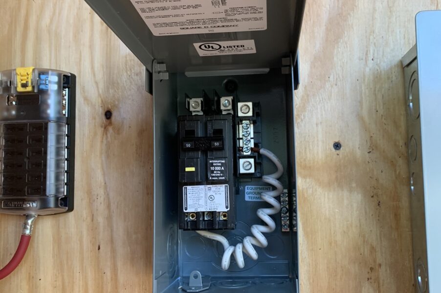
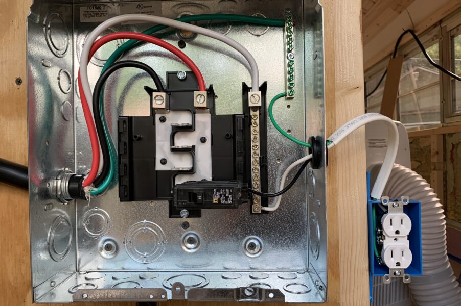
In our install I entered the box from the left. The black and red wires will need to be installed on the two terminals above the breaker. It does not matter which ones as both are hot, but it will be good to maintain the same order where the power exits the breaker on the bottom. The white wire will run to one of the terminals on the common bus bar. In the image below it is immediately to the right of the breaker, and if this is a GFCI breaker (which I’d recommend), there will already be one connection from this bar to the breaker. You can see that in the first image. The green wire will go to the bus bar with the green screws. You may need to install one. Ours is on the right almost behind the white wire in the first picture.
You’ll likely want to use as little wire inside the box as possible. I needed to use pliers because it was not easy manipulating these wires in such a small space, but with patience it can be done. But once the wires are in the terminals, you can screw them in with a flathead screw driver to clamp the wires down. It is important to make sure all the wires enter the clamp. You do not want any stragglers shorting the power.
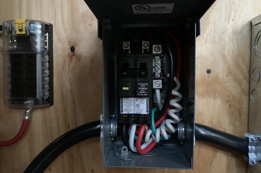
Next we need to do the same thing coming out. Using another length of 50 amp wire, the black and red wires will be clamped at the bottom of the breaker. The white wire also exits at the bottom as seen in the images above. This is a separate white wire than the one that came attached. The green wire will connect on the same ground bar as the incoming wire and the whole thing will exit the box through a wire clamp.
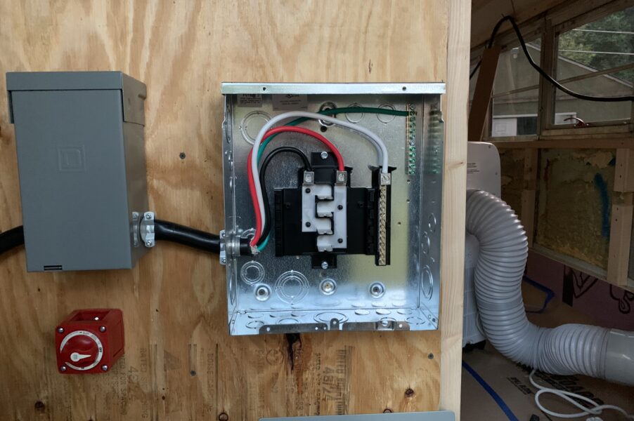
Wire the first panel to the second panel
After exiting the first 50 amp panel with 50 amp wire, we’re going to wire into our second 125 volt panel. This is where we will actually wire breakers and create circuits that make their way through the rest of our build. Using another wire clamp, the 50 amp wire will enter this panel much like it did the first. Same as the first panel, our white wire will go straight to the common bar and the ground wire to the ground bar. You may need to install a ground bar. The black and red wires will go to the two remaining terminals. Again I like to go in the same order as we did in the 50 amp box, but it will work either way. These are the two hot wires which will provide power to the installed breakers. Every other single pole breaker will use one or the other leg of power. Breakers providing 240 volts would make a connection on both legs. You’d only need that if you planned on having an electric oven and range or a clothes dryer or something. More likely than not a couple 15 amp breakers to power lights and outlets will be sufficient. Clamp everything down and we’ll be ready to create a circuit and power a light or outlet.
Running a circuit
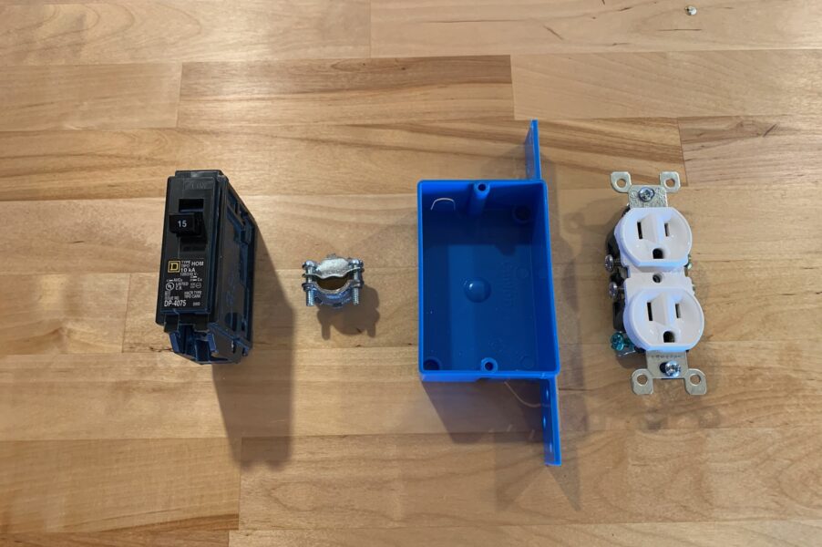
Now that we will have power running to this panel, it is time to create a circuit. You’ll need a circuit breaker, some marine wire, an outlet box, and an outlet. As far as tools you’ll need a wire cutter and stripper, and a screw driver.
Every circuit will need the green wire to the ground bar, the white wire to the common bar, and the black wire to the circuit breaker. The circuit breaker will slide into the panel and make a connection to one of the posts running down the middle. The wire will exit the box through a wire clamp. These can and should be much smaller than the ones used for the 50 amp wire. In most of the pictures you’ll see we are using grommets instead of wire clamps. I recommend wire clamps over the grommets we used.
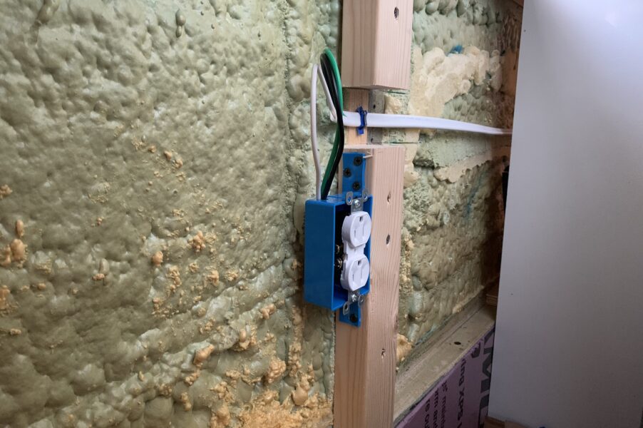
Install an outlet box wherever you like. I was so excited to test our system I just put a temporary one right next to the 125 volt panel. Run the marine wire into the box and wire each wire to the outlet. The back wire goes to the gold screw and the white wire to the silver screw. There should be a green screw for the ground as well. Screw the outlet into the outlet box and be sure to cover it if you plan to leave it.
Pro Tip: Since we are using stranded marine wire instead of traditional solid wire, I recommend being very deliberate with all your connections. Stranded wire does not behave as well as solid wire when using a screw for the terminal. I have found that if you strip the wire, then strip another smaller length and slide it to the end, but not off the wire, you’ll find it behaves a little bit better. I will try to get a better picture on this method.
If you followed this guide, your electrical system should look something like this. An inlet in the side of your vehicle, wired with 50 amp wire to a 50 amp spa panel, to a 125 volt breaker box. Any breaker installed here are run to an outlet or light and we have no loose wires anywhere.
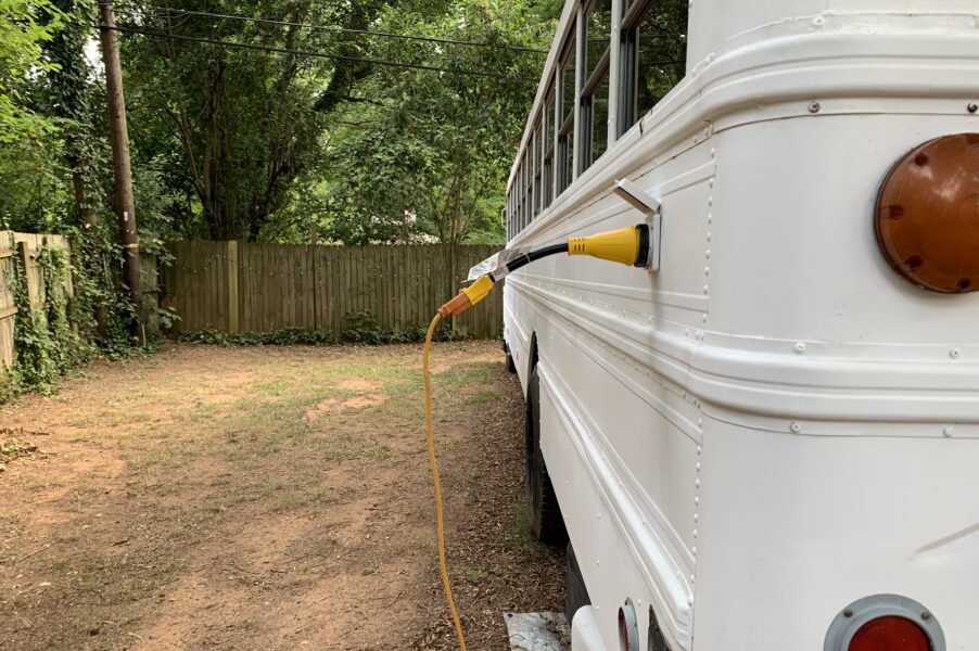
Testing your electrical system
If everything is wired correctly you can test your system. We definitely do not have 50 amp service in our back yard, and I wouldn’t want to test with that first anyways, so we used a 15 amp to 50 amp adapter to run a regular extension cord to our 50 amp inlet.
The adapter screws in to the inlet to make the connection. There is also a plastic ring that will ensure no water gets in to the connection.
Once again its pretty important you fully understand what is happening in your build. Do not plug the adapter in to a power source unless you are 100% sure you have wired your system correctly. If you are unsure you must have an electrician review your work.
If everything is wired correctly, when you plug the extension cord in you will really have just made your extension cord a little bit longer (and a lot heavier). Test the outlet with something small or preferably with a switch of its own. A lamp would work well. Even better, you can get an outlet tester pretty inexpensively from Home Depot or Amazon.
Congratulations! Thats about it. Im sure there are a number of other circuits you’re going to install from here. Good luck with your build!


 by
by